

I learned this the hard way. Three days before a fintech hardware launch, our payment terminal failed pre-compliance EMC testing. Spectral emissions were off the charts. The launch slipped six weeks, and the final bill ran ten times what an early scan would’ve cost.
That’s when I stopped treating testing as a final checkbox and started treating it as insurance. Whether you’re shipping a consumer gadget, an IoT sensor, or embedded hardware for financial terminals, this electronic testing guide covers what actually matters. No fluff. Just the testing stages, tools, and mistakes that separate products that ship from products that get recalled.
Electronic testing is the systematic process of verifying that a component, circuit, or finished device performs as designed, operates safely, and meets regulatory requirements — from the first resistor you inspect to the final certification lab.
Table of Contents
What Electronic Testing Actually Covers
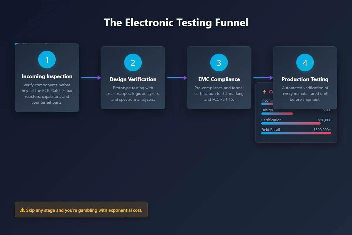
Testing isn’t one thing. It’s a funnel. You check parts before they hit the board. You verify the prototype works. You certify the final design. Then you test every unit that rolls off the line. Skip any layer, and you’re gambling.
The goal is simple: catch problems while they’re cheap. A bad resistor caught at incoming inspection costs pennies. The same resistor inside a finished product means rework or scrap. If it gets to a customer, you’re looking at field failures or a full recall. The cost curve isn’t linear — it’s exponential.
Here’s something simulation won’t tell you. SPICE models predict ideal behavior. Measurements show reality. And reality doesn’t always agree. I’ve seen circuits that simulated perfectly and failed on the bench because a trace length, a connector, or a grounding issue wasn’t in the model. You can’t simulate the physical world perfectly. Testing is what bridges that gap.
Most teams break testing into four stages: incoming inspection, design verification, compliance certification, and production validation. Each stage uses different tools and catches different failure modes. Treat them as a chain, not separate departments.
Component-Level Electronic Testing Methods
Before a component lands on your PCB, verify it. Most incoming inspections find nothing unusual. That doesn’t mean you should skip them. One defective batch from a new supplier can justify years of checks.
A digital multimeter handles the basics: resistance, voltage, current, continuity. An LCR meter adds inductance and capacitance, often at multiple frequencies. Frequency matters. A capacitor that looks fine at DC can behave completely differently at its operating frequency. That shift can break filters, destabilize power supplies, and throw off RF matching.
Static testing looks at a component without running signals through it. Dynamic testing exercises it under real operating conditions — frequency response, power handling, thermal drift. Parametric testing checks every measured value against the datasheet limits. The method you choose depends on what you’re afraid of failing.
In fintech hardware, we’ve caught counterfeit regulators this way. They looked identical. They weren’t. The parametric test showed a dropout voltage 40% higher than spec. We caught it before production. That’s the difference between a $0.05 part and a $50,000 field failure.
Design Verification: The Tools That Matter
Once the prototype exists, you need to see what’s actually happening. Not what you think is happening. These are the electronic testing tools I reach for first.
Oscilloscope. It’s the fastest way to see voltage and timing. Glitches, noise, overshoot, transients — things that don’t show up in simulation. Some faults are intermittent. A modern scope with deep memory catches events you’d never see otherwise. Mixed-signal scopes add digital channels so you can watch analog waveforms and protocol activity side by side.
Logic analyzer. Essential for digital buses. Instead of guessing what two devices are saying, you capture the actual I2C, SPI, UART, or CAN traffic. In my experience, about half of “communication bugs” aren’t protocol errors at all. They’re timing issues, power dips, or incorrect pull-ups. The logic analyzer tells you which half you’re in.
Spectrum analyzer. Shows signal power across frequency. Critical for switching circuits, wireless modules, and anything that needs EMC certification. It reveals energy at frequencies you won’t see in the time domain. That hidden energy is what gets you fined.
Vector network analyzer (VNA). For RF work, this is non-negotiable. S11 and S21 parameters expose reflection, transmission loss, filter shape, and impedance mismatch. An RF design can simulate perfectly and still fail because of PCB trace geometry, connector losses, or manufacturing tolerance. The VNA finds those gaps.
EMC Compliance Testing
This is where I lost six weeks and a lot of money. EMC testing asks two questions: what electromagnetic noise does your device emit, and how well does it survive interference from the outside world?
Emissions testing splits into radiated and conducted. Radiated means energy flying through the air. Conducted means unwanted noise traveling down cables and power lines. Immunity testing flips the script: you blast the device with ESD, transients, surges, and RF fields, then check if it still works.
These aren’t optional. Europe requires CE marking for electromagnetic compatibility. The U.S. requires FCC Part 15 compliance. Other markets have their own frameworks. You can’t ship without them. The FCC’s equipment authorization database publishes the exact limits, and they’re not suggestions.
Pre-compliance testing is your early warning system. It doesn’t replace formal certification. But a spectrum analyzer and a set of near-field probes can spot major emissions problems while a layout change still costs hours, not weeks. The certification lab is for confirmation. Pre-compliance is for survival.
If you’re building anything with a switching regulator, a wireless radio, or a high-speed processor, run a pre-compliance scan before you finalize the PCB. It’s the cheapest insurance you’ll ever buy.
ESD Testing and Hidden Damage
Electrostatic discharge isn’t always dramatic. Sometimes it’s a tiny spark you don’t feel. Sometimes it causes instant death. Other times it creates latent damage — the component passes every test today and fails mysteriously next month in the field.
IEC 61000-4-2 defines the standard test methods: contact discharge and air discharge. Contact is more repeatable. Air discharge mimics real-world scenarios where a charged finger approaches a surface. Both matter.
ESD protection gets designed in — TVS diodes, proper grounding, careful PCB layout. But designing protection and proving it works are two different jobs. I’ve seen boards with protection circuits that looked great on paper but failed the test because the ground path was too long. Testing is the only way to know.
Production Testing at Scale
Design verification proves the design works. Production testing proves every single unit works.
At volume, manual electronic testing doesn’t scale. Automated test systems power up the product, apply inputs, measure outputs, compare against limits, log data, and flag failures in seconds. But automation isn’t magic. A test program is only as good as the spec it’s built from.
Here’s a painful truth. A test system can pass a thousand units while completely missing a critical parameter. How? If the parameter wasn’t in the test plan, it wasn’t measured. I’ve seen this happen. The problem surfaced in field returns. When we reviewed the production test spec, the affected parameter was simply absent. Not failed. Absent.
A good production test plan starts with failure modes. What can break? Which measurement catches it? What’s the tolerance? Is the equipment accurate enough to make that call? Answer those before the first unit hits the line. For teams scaling hardware, our sensor testing coverage breaks down hardware validation strategies in more detail. If you’re building your first bench, see our oscilloscope guide for budget-friendly instrument picks.
Calibration: The Trust Chain
Your electronic testing instruments lie. Not on purpose. They drift. Temperature, age, usage, drops, overloads — all of it nudges readings away from truth. An instrument that was calibrated last year might not be trustworthy today.
Calibration compares your instrument against a traceable reference. The standard must be far more accurate than the unit being tested. That’s how confidence propagates down the chain. For U.S. labs, NIST maintains the national traceability chain that makes those measurements credible.
In production, a drifting instrument is dangerous. It can start passing bad units or failing good ones. Nobody notices immediately. By the time you catch it, a batch might already be compromised. Track calibration status actively. Don’t just trust the sticker.
Where Testing Programs Fail
The most expensive mistake is testing too late. By the time you’re at formal certification, you’ve already burned months and budget. A core flaw found there means redesigns, new tooling, missed launches, and angry customers.
Inadequate test coverage is the silent killer. A test plan that passes everything isn’t a good test plan. It’s a blindfold. If you never measure a parameter, you never know it’s wrong.
Skipping pre-compliance EMC is another gamble. Sometimes you get lucky and pass certification cleanly. When you don’t, the cost dwarfs what a spectrum analyzer and a few hours of engineering time would’ve cost.
And calibration assumptions will bite you. “It was calibrated last year” isn’t proof. It’s hope. Track it. Verify it. Or don’t trust the numbers.
Key Takeaways
- Electronic testing is a funnel — incoming, design, compliance, production. Skip a layer and you gamble.
- Pre-compliance EMC scans are cheap insurance compared to failing formal certification.
- A passing test plan doesn’t mean you’re measuring the right things. Coverage beats quantity.
- Calibrate your instruments actively. A drifting meter silently ships bad products.
- Simulation predicts. Measurement confirms. Reality wins when they disagree.
Frequently Asked Questions
What is the difference between EMC emissions and immunity testing?
Emissions testing measures the electromagnetic noise your device generates — both through the air (radiated) and through cables (conducted). Immunity testing checks whether your device survives interference from outside — ESD, surges, RF fields, and electrical transients. One evaluates what your device puts into the environment. The other evaluates how well it survives that environment.
Why does a device pass functional tests but still fail EMC certification?
Functional testing checks whether the device does its job. EMC testing checks whether it plays nicely with other devices in the electromagnetic environment. A product can work perfectly while spewing interference above legal limits. The two tests measure completely different things. That’s why you need both.
How often should test equipment be calibrated?
Most manufacturers recommend annual calibration for lab instruments. But the right interval depends on usage, environment, and required accuracy. Instruments used for production decisions need tighter control. If an instrument was dropped, overloaded, or exposed to extreme conditions, check it before you trust it for critical measurements. The sticker on the side is a starting point, not a guarantee.
What is pre-compliance EMC testing, and is it worth doing?
Pre-compliance testing is an early engineering check you do in-house before sending a product to a formal certification lab. A spectrum analyzer and near-field probes are often enough to spot obvious emissions issues. It won’t give you a certificate, but it will tell you if your design has a problem while changes are still cheap. For most hardware products, it’s absolutely worth doing.
Which test instrument should I buy first for a small electronics lab?
Start with a good digital multimeter and a bench power supply with current limiting. Those two cover the basics and protect you from wiring mistakes. Next, add an oscilloscope — it’s the single most useful debugging tool for prototypes. Only add a spectrum analyzer or VNA when you’re working on RF, wireless, or EMC-sensitive designs. Build your bench based on what you’re actually shipping.
Related Reading: Electronics Manufacturing: How I Scaled from Prototype to 10,000 Units | Intel Rapid Storage Technology: Do You Actually Need It?
